Fatigue fracture
Fatigue fracture surfaces possess quite a unique characteristic of flat surfaces with limited plastic deformation and in some cases show visible beach mark as shown in the gear teeth subjected to fatigue failure in figure 12. Surface condition is a prime factor in controlling surface crack initiation. Crack or defect-free surfaces greatly help to improve fatigue life of the components. Rough surfaces are also attractive to stress concentration, leading to easy fatigue crack initiation.
In general, initiation and propagation of the fatigue crack can be divided into three stages, 1) Fatigue crack initiation Bstage I, 2) stable fatigue crack propagation-stage II and 3) Unstable fatigue crack initiation B stage III. The initiation of the fatigue crack is sensitive to surface conditions. Figure 12 shows mechanisms of extrusion and intrusion on the top surface of sample subjected to fatigue loading. Persistent slip planes caused by back and forth motion of fatigue produce a number of extrusions and intrusions as illustrated in the schematic diagram. The latter is considered as an atomic scale notch and acts as a stress raiser to eventually become the initial fatigue crack on such a surface. The plane of the fatigue crack at this stage is along the shear plane or slip plane. When the fatigue crack grows a little further, the fatigue crack is now influenced by the tensile stresses which are perpendicular to the crack propagation direction. The fatigue crack is now said to be in the stage II region, and propagates at a relatively stable rate. The fatigue propagation rate in this region therefore represents the fatigue crack growth of the specimen. The final stage is the unstable fatigue crack propagation which takes place when the fatigue crack length exceeds the critical length for stable crack growth, leading eventually to fatigue failure.
If we study the stage II fatigue fracture surface using SEM technique, striations orientated normal to the fatigue crack growth direction as shown in figure 14 (a) will be observed. Each striation is due to plastic blunting process as demonstrated in figure 14 (b). When the tensile loading progresses, the crack opens and allows the slips to operate at the top and bottom ends to produce local plastic deformation as shown by the arrows. At a higher tensile loading, plastic blunting occurs, which leads to an increase in the fatigue crack length. During unloading, the fatigue crack is then closed and the slips are now operating in the opposite direction. Therefore, after one cycle, the fatigue crack now arrives at the original stage of crack closing with an increase in one fatigue striation.
Figure 12: Beach mark observed on a fatigue fracture fracture surface of gear.

Figure 13: Mechanism of extrusion and intrusion on the top surface due to persistent slip bands [1].

Figure 14: a) Fatigue striations in aluminum and b) Fatigue striation due to plastic blunting process.
Furthermore, the fatigue failure can be found to occur in conjunction with corrosive and high temperature environment, which are called corrosion fatigue and thermal fatigue respectively. Corrosion and high temperature accelerate the rate of the fatigue crack propagation and promote severe fatigue failures. An example of corrosion fatigue shows obvious areas of rust on the fatigue surface observed in an automobile shaft as depicted in figure 15 (a). This significantly reduces the fatigue life of the automobile shaft. Thermal fatigue illustrated in figure 15 (b) shows a beach mark which indicates the fatigue crack initiation to have started at the top surface.

Figure 15: Fracture surfaces of specimens failed in a) corrosion-fatigue and b) thermal fatigue.
FRACTURE SURFACES OF HIGH Mn STEEL AFTER CHARPY IMPACT TEST
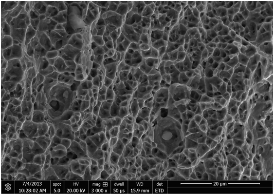
This is fracture surface of high Mn steel sample after rolling which shows a combined brittle and ductile fracture. The features are many ductile dimples, voids indicating the ductile failure, and cleavage planes (flat planes with small atomic steps indicating brittle fracture).

This is a fracture surface of solution annealed high Mn steel sample shows a complete ductile fracture having small and uniform dimples.
Ductile fracture and Micro structure of Nonporous Gold
Gold has been known since prehistoric times
It is a soft metal with a characteristic yellow colour. Gold is the most malleable and ductile of any element. It is unaffected by air, water, alkalis and acids, with the exception of “aqua regia”, HNO3/HCl. The fact that it is chemically unreactive means that it is often found in its natural state. Gold is a good thermal and electrical conductor and has excellent reflective properties to both light and infrared. It has an abundance in the earth’s crust of 0.0011 ppm.
Most of the metal is retained for use as bullion reserves, but some is used within the electronics and jewellery industries, where it is frequently alloyed with other elements to improve the mechanical properties of the metal (e.g. copper and silver). Other uses for Gold are as a heat reflecting coating for glass as well as as a decorative medium
 |
FIG. 1. Microstructure and fracture appearance of nanoporous Au shown at different magnifications. (a)Low-magnification SEM micrograph revealing a combination of transgranular (featureless region I) and intergranular brittle fracture(rock candy region II). (b) Boundary region between transgranular (region I)and intergranular fracture (region II) at higher magnification. (c) A close-up of the outlined area in(b) reveals the ductile nature of the fracture:
the ligaments fail by necking due to overloading. (d)Region I (transgranular) and region II (intergranular) are separated by two-dimensional, void-like defects (marked by arrows) that serve as crack nucleation sites.
|

Figure 2
|
FIG. 2. SEM micrographs showing crack formation during high-load Vickers indents (300 g). (a) High magnification micrograph from a crack tip region showing highly strained ligaments bridging a microcrack. Elongations in the order of 100% have been observed. (b) Detail of a larger crack revealing pronounced necking prior to failure.
|

Figure 3
|
FIG. 3. Fracture surface of a np-Au sample that had been heat treated for 2 h at 570 °C prior to fracture at room temperature. The heat treatment
increases the pore size/ligament diameter from ~100 nm to ~1micro m.(a) Extensive plastic deformation is observed in a larger region around cracks:
cell collapse in regions of compressive stress (cs), and elongation of the cell structure in regions of tensile stress (ts). (b_ A higher magnification view of the area within the rectangle reveals plastic deformation of individual ligaments by slip (sb)
|
On a microscopic level, however, characteristic neckingfeatures reveal ductile fracture due to overloading of individual ligaments [Figs. 1(b) and 1(c)]. The macroscopically apparently featureless regions (I) of the fracture surface are microscopically very rough and exhibit a high density of disrupted ligaments, whereas the rock candy regions (II) have a very smooth appearance with only a few disrupted ligaments. Extended two-dimensional void-like defects are observed at the boundary between rock candy (II) and featureless(I) fracture surface regions[Fig. 1(d)]. These defects seem to have their origin in a Ag enrichment along the grain boundaries of the original Ag–Au alloy: dealloying of the silver-enriched material leads to the development of a reduced density (voids) along the original grain structure. Indeed, Ag surface segregation during annealing has been reported for the Ag–Au system.19 Thus rock candy regions of the fracture surface are produced by intergranular fracture (intergranular with respect to the grain structure of the Ag–Au starting alloy), and featureless regions indicate transgranular fracture (through the grains of the Ag–Au starting alloy)
The two-dimensional (2D) void-like defects discussed earlier presumably act as crack nucleation sites due to local stress enhancement. Ligaments connecting the regions on opposite sides of a defect experience the highest stress fields and are the first to fail. In case of a penny-shaped defect in a three-dimensional cubic network, the local stress enhancement would be proportional to n1/4, where n is the number of missing ligaments.20 Once an unstable crack is formed, the crack propagates along the 2D defects until intersecting with another 2D defect at an oblique angle, where the fracture may or may not switch from “intergranular” to “transgranular.”
The deformation of np-Au in the vicinity of crack tips was further studied by controlled introduction of microcracks via high-load Vickers indents (load of 300 g, maximum indentation depth ~35 micro m). SEM micrographs reveal that microcracks nucleate and propagate along the indenter edges where the stress is concentrated. Individual ligaments, still bridging the crack, can be observed in the vicinity of the crack tips[Fig. 2(a)]. Some of these ligaments are strained by as much as 200%. High magnification micrographs of larger cracks formed in the same area reveal pronounced necking prior to failure [Fig. 2(b)]. The observation of ligaments bridging microcracks suggests that, on a nanometer length scale, the elongation to failure is on the order of 100%, which is a remarkable result in the context of the macroscopic brittleness of np-Au. However, the observed high strain values are consistent with the fact that Au is the most malleable metal, and indeed even higher strain values might have been expected. Nevertheless, microscopically, np-Au is a very ductile material, despite its apparent macroscopic brittleness.
Annealing of np-Au leads to an increase of the length scale of the structure, and thus allows one to study cell-size effects. For example, annealing at 570 °C for a period of 2 h increases the pore size/ligament diameter from ~100 nm to ~1 micro m. Changes of the fracture mechanism were studied by SEM (Fig. 3). Overall, the fracture morphologies of annealed and unannealed samples are very similar; that is, both featureless (I) and rock candy (II) regions can be observed. However, in the case of the annealed sample, extensive plastic deformation of the nanoporous structure occurs in a larger region around cracks; cell collapse in a layer-by-layer mode indicates regions of compressive stress, and elongation of the cell structure reveals region of tensile stress [Fig. 3(a)]. In addition, plastic deformation of individual ligaments by slip can be detected [Fig.3(b)]. The slip bands (sb) indicate slip on the {111} planes in <110> direction. It should be emphasized that slip bands were not observed on fracture surfaces of as-prepared np-Au samples [see, e.g., Fig. 2(b)]. Slip plays an important role in the rupture process of thin Au wires; successive slip events on two or more slip systems can lead to necking and failure.The larger degree of plastic deformation on fracture surfaces of annealed samples indicates strengthening of the network structure. We attribute this to the annealing process, which allows sufficient diffusion (Ostwald ripening) to eliminate the two-dimensional defects that serve as crack nucleation sites. Indeed, SEM reveals that the two dimensional void-like defects typically observed in as prepared np-Au samples collapse during annealing, thus fusing weakly connected regions of the network together.
What causes the macroscopic brittleness of np-Au, although it is microscopically a very ductile material? In analogy to the case of a random fuse network analyzed by Kahng et al., “brittle” failure can be expected for a sufficiently narrow ligament-strength distribution, regardless if the ligaments fail microscopically in a ductile or in a brittle manner. In the limit of a narrow ligament-strength distribution, rupture of the weakest ligament initiates the catastrophic failure of the network structure by overloading adjacent ligaments. The unstable crack then propagates quickly through the bulk of the material following the path of least resistance. This interpretation is consistent with the narrow pore size/ligament width distribution of np-Au, which implies a uniform failure strength.
The overall strength of a randomly fused network is determined by the largest “critical” defect; that is, the defect that causes the highest stress enhancement at its edge. In the present study, two-dimensional void-like defects serve as crack nucleation sites by concentrating the stress on adjacent ligaments. Thus, instead of plastic deformation of the whole sample, the failure of a few ligaments triggers the brittle fracture of the network. Interestingly, the failure mechanism of the ligaments seems to change with the length scale. Microscopic characterization of fracture surfaces of as-prepared np-Au with a ligament diameter of ~100 nm suggest that the ligaments fail by plastic flow and necking. On the other hand, failure by slip was observed for ligaments with a diameter of ~1000 nm. The latter observation indicates dislocation activity as the stress required to cause slip is reduced by several orders of magnitude by the presence of dislocations. The absence of slip marks on fracture surfaces of as-prepared np-Au suggests that the dislocation activity is suppressed by the nanoscale ligament/grain structure. A suppressed dislocation activity at the submicron scale is also consistent with the high strength observed for nanoporous Au, Au nanocontacts, and submicron Au pillars.
In conclusion, this study demonstrates that the macroscopic brittleness of np-Au arises from the network structure rather than reflecting a microscopic brittleness. This result may be used to improve the mechanical properties of nanoporous Au; namely, by introducing a broader ligament strength distribution and by eliminating two-dimensional defects.
MILD STEEL
Iron carbon alloy containing less than 0.25 percent carbon which makes it more ductile and less
hard thus rendering it unsuitable for structural work
It is tough, ductile, malleable, good tensile strength, poor ressistance to corrosion.
Microscopic study of fracture path
In order to identify the exact crack path and the mechanism of failure of the mild stee materiall containing the machined holes, the specimens were not allowed to fail completely. The region ahead of the growing crack was sectioned, and thinned by the surface grinder. These were mounted in thermosetting resin, polished, etched and then observed under the microscope to investigate the exact crack path. The microphotograph of one such sample is shown in Fig. 1. In microscopic level, propagation of crack is not truly linear, it is zig-zag. As discussed by Stec and Faleskog [5], due to differences in orientation of cleavage planes of two neighbouring grains, crack changes its direction when it advances from grain to grain. Grain deformation at regions away from the holes is not evident. However, extensive elongation of grains indicating large plastic deformation is evident at regions adjacent to the holes. The grain elongation is maximum at the regions of propagating of crack surfaces (Fig. 2). Due to these large elongation of the grains, compatibility between adjacent grains are lost at grain boundary regions resulting in the formation of sharp defects/cracks at these regions. Submicroscopic cracks were found nucleating at grains boundary regions only (a few isolated voids were observed inside the grains). The voids at regions of grain boundaries are large in number (Fig. 3). The main crack propagated through regions of high void population leading to a zigzag pattern when observed at a microscopic level. Voids nucleated ahead of the growing crack coalesce before they joined the main crack (Fig. 4 and Fig. 5). Stress intensity factor near the crack tip plays an
important role for void growth and coalescences. This coalescence of the sharp micro-cracks ahead of the main crack leads to very high stress concentration facilitating the fracture process. In some cases, instead of single crack propagation, two or more cracks may be formed simultaneously and later they joined with each other by joining intermediate voids as shown in Fig. 6.

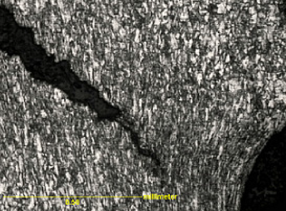
Fig 1 fracture path under microscope Fig 2 grain in front of crack tip
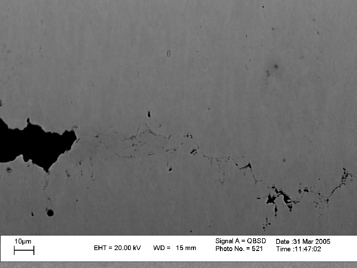
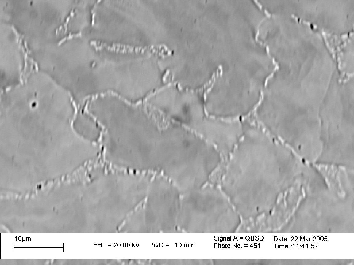
Fig 3 voids present at grain boundary Fig 4 void coalescene in front of crack


Fig 5 void coalescene in front of crack Fig 6 multi-crack formation
For specimen with smaller holes (of size 0.5mm), slip phenomena are observed as shown in Fig. 7. In this case, during slipping, load increases slightly and then decreases when fracture starts. As a very close approximation, the slip or glide can be considered analogous to the distortion produced in the pile of cards when it pushed from one end. Slip phenomena occur due to micro voids and dislocation movement in the materials. That slip phenomena promote for crack formation and propagation, which may be considered as Mode-II fracture
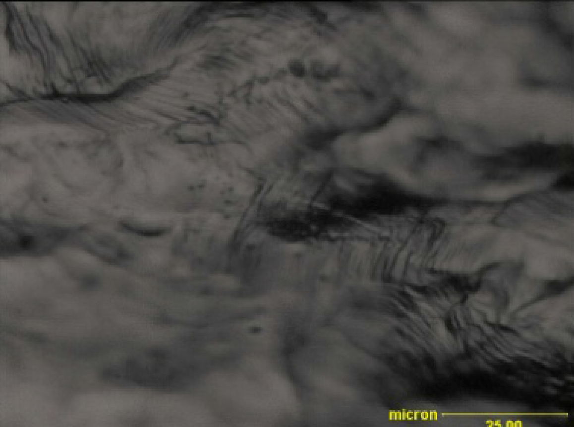

- Slip plane area near bottom most hole (b)crack tends to form by slip plane