Ductile fracture
If we now consider a tensile sample which is loaded beyond the maximum tensile strength as shown in figure 7, we can see necking occurring along the specimen gauge length. Within the necking area, microvoids are formed probably around the particles. As the load continues, these microvoids expand and join together to create a crack with its plane perpendicular to the axis of the tensile force applied. As this crack grows, the shear plane of approximately 45o to the tensile direction develops around specimen edge and merges with the existing crack, resulting in the classic cup and cone fracture surfaces as demonstrated in figure 7. Ductile materials normally exhibit gross plastic deformation during fracture, providing rough fracture surfaces with relatively high surface areas as has been illustrated in figure 1. Ductile fracture therefore requires higher energy to create two new fresh fracture surfaces in comparison to energy required to cleave flat brittle surfaces. Investigation under higher magnifications shows ductile fracture surface consisting of copious of ductile dimples or microvoids. The mechanism of microvoid formation is demonstrated in figure 8, showing the influence of inclusions or second phase particles as microvoid initiation sites. During loading, these particles decohere from the matrix, forming a microvoid around each particle. Continuing the applied load results in the expansion of these microvoids and finally leads to microvoid coalescence, giving the complete failure. Generally, these microvoids are normally observed to be centred on inclusions or second phase particles as shown in figure 8 (d). Materials such as ductile cast iron, aluminium or alloys operating at high temperature exhibit this type of fracture surface.

Figure 7: Cup and cone fracture.
Furthermore, the shape of the microvoids observed in a microscopic scale can be used to determine the type of the force applied on to the specimen. If the microvoids are in equiaxed shape, as shown in figure 9 (a), the applied force are uniaxial tensile loading. Parabolic-shaped microvoids with its tip pointing in the opposite direction when seen on both halves of fracture surface are due to shear force, see figure 9 (b). If the microvoids appear in the parabolic shape with the tip of each microvoid orientated in the same direction on both fracture surface halves, the tensile tearing is applied in this case as shown in figure 9 (c).
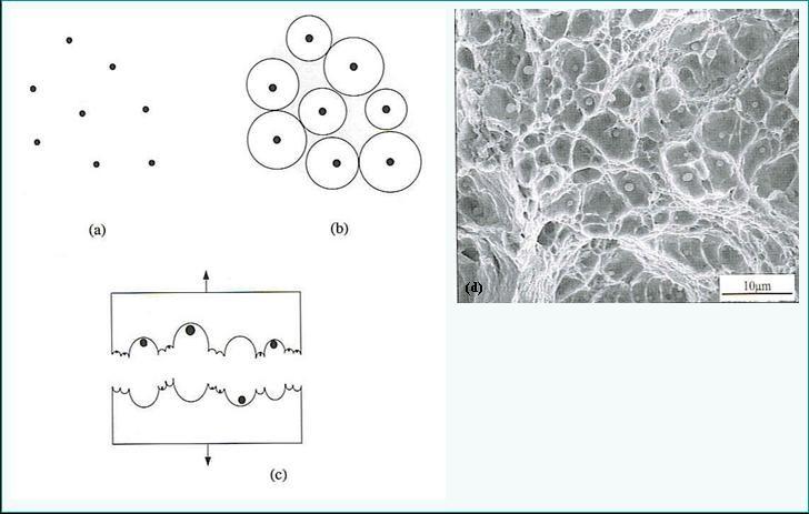
Figure 8: Microvoid coalescence in ductile fracture[4].
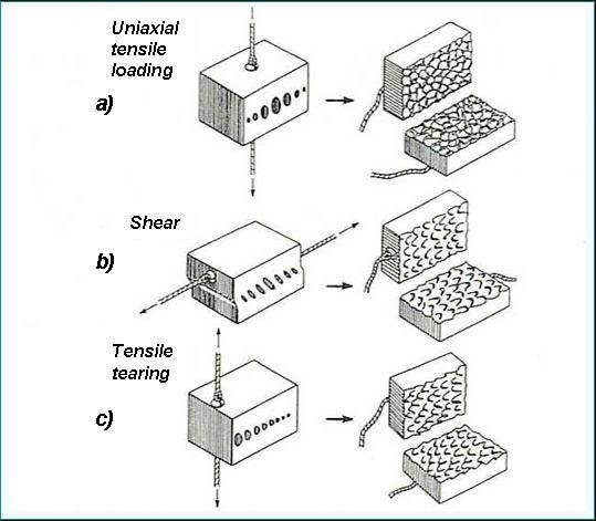
Figure 9: Different characteristics of microvoids observed under (a) Uniaxial tensile loading, (b) shear and (c) tensile tearing.
Intergranular fracture
Intergranular fracture is normally associated with service conditions which are corrosive or high temperature. These conditions resulting in precipitation of the second phase particles along the weakened grain boundaries. Figure 10 illustrates two types of intergranular fracture; a) intergranular fracture with microvoid coalescence and b) without microvoid coalescence. Although the former exhibits areas of ductile dimples similar to those observed from typical ductile fracture surfaces, these ductile dimples are relatively shallow and require much less energy involved in the fracture process. These ductile dimples or microvoids are formed around particles precipitated in some cases as a network along the grain boundaries. This considerably reduces the bonding between the particles and the matrix, which in turn allows microvoid coalescence to occur more readily. As a result, the material has significantly reduced fracture energy which promotes a rapid crack propagation path along the grain boundaries.
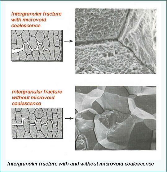
Figure 10: Fracture surfaces of (a) Intergranular fracture with microvoid coalescence and (b) without microvoid coalescence.
Temperature is one of the most important factors influencing intergranular fracture. High temperature not only facilitates ductile failure (increased amount of plastic deformation) but also promotes metallurgical changes. If the bonding between the new phases and the matrix is quite poor, responses of materials to external loads will be significantly affected, which can subsequently alter the fracture mode of the materials. In general, oxidation or combustion reactions are involved when materials are subjected to high temperatures, such as in the case of turbine blades. Oxide scales on the metal surface are normally brittle and heterogeneously formed, leading to a crack formation on the surface. If the load continues at high temperature, oxidation would progress even further into material interior through the existing surface cracks. This might result in the formation of brittle oxidation products within the grain and especially along the grain boundaries. If these grain boundary oxidation products are interconnected and poorly bonded with the matrix, intergranular fracture will result. Therefore, it can be seen that although high temperature promotes ductile failure, metallurgical changes might alter the fracture mode from transgranular ductile fracture to intergranular fracture due to poorly bonded grain boundary particles. This embrittlement effect results in noticeable reductions in tensile strength and ductility. The utilization of the materials at high temperatures or strong oxidation will considerably affect mechanical properties of the materials. Material selection therefore becomes significantly important in this case. Nickel based alloys are a good alternative for service conditions at high temperature and oxidation. Furthermore, material which is subjected to corrosive environment where corrosion products are observed along the grain boundaries will give comparable results.
No comments:
Post a Comment